
|
|
|
#31
 11-20-2017, 02:31 AM
|
|||
|
|||
|
Marcus
Do realise you are taking the "Rat" out of this Ratrod, but somehow I think this your plan. Bare metal and door sills on the ground would nice. Well done again Marcus
__________________
"Hillman" 
|
|
#32
11-20-2017, 05:23 PM
|
||||
|
||||
|
Many thanks Tom and John.
 Quote:
 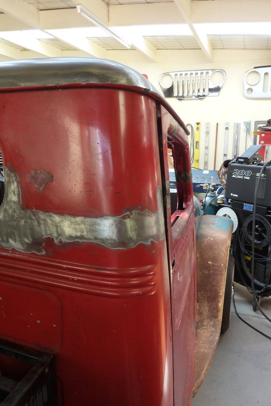 After doing all the adjusting I could on the hinges and forcing the top of the frame over, it was still hanging outwards at the top if the rest of the door was in line. 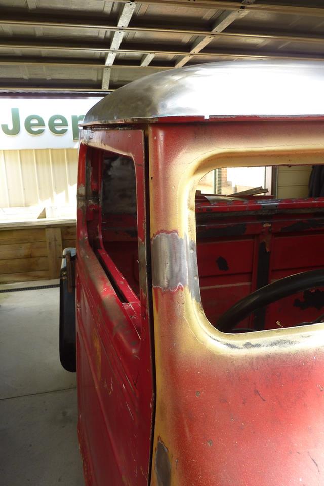 The front was the same although not as bad. 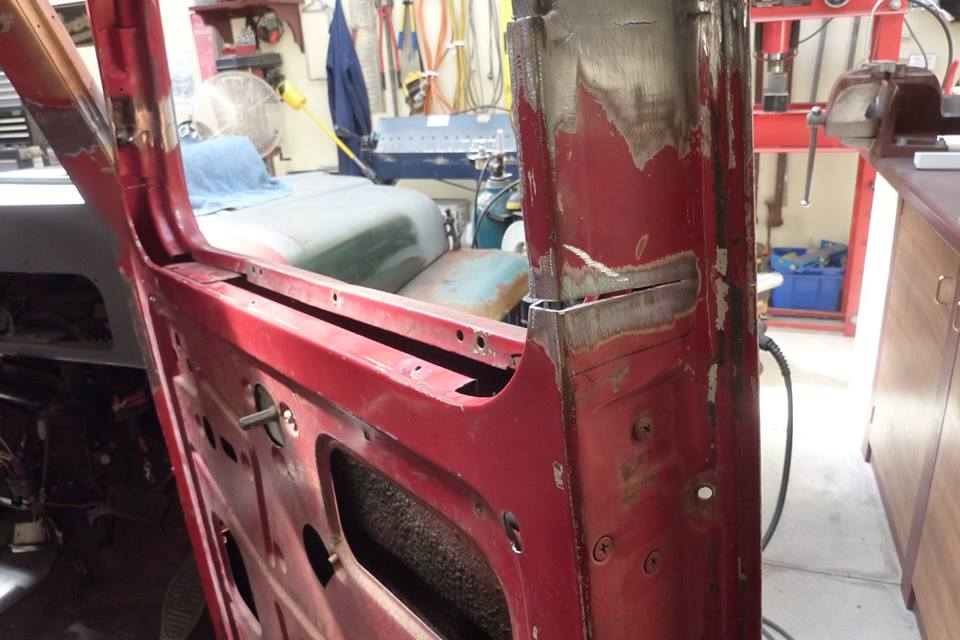 A wedge was cut into the frame where the bend was needed. 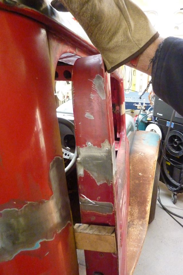 Pushed over and tacked. Then checked to see if it was enough. Remember it will pull a few millimetres more with the weld shrinkage, so allow for that to save stretching the weld afterwards  Welded up.  Looks a lot better now.  Front was also done. 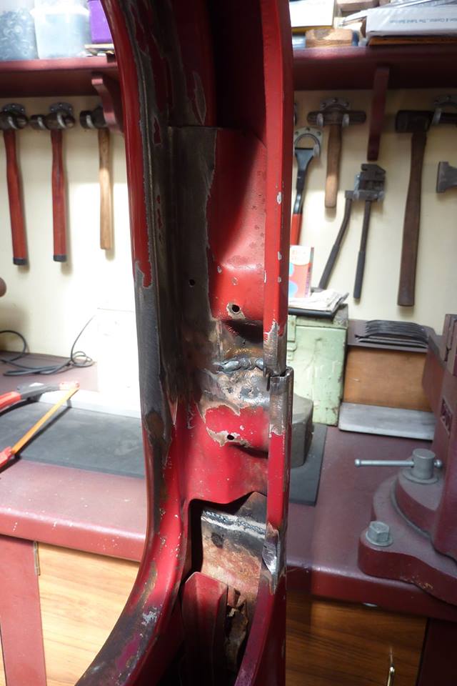 Now this difference in width of the window frame needs to be dealt with. The frame had a slight taper to it so it shows up once the 5.5" was chopped out. 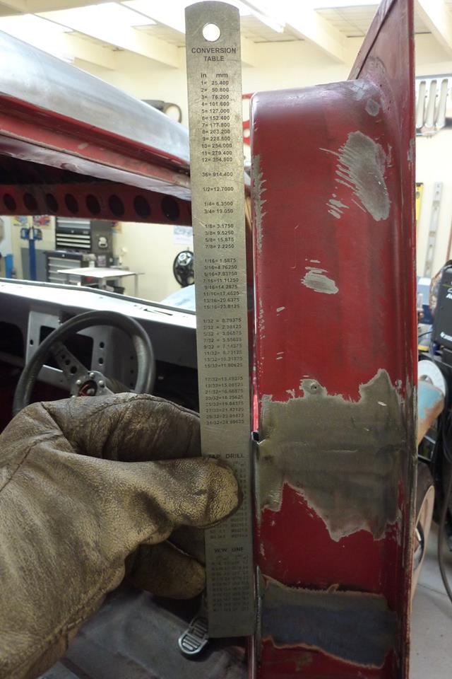 Can see it better from this angle. 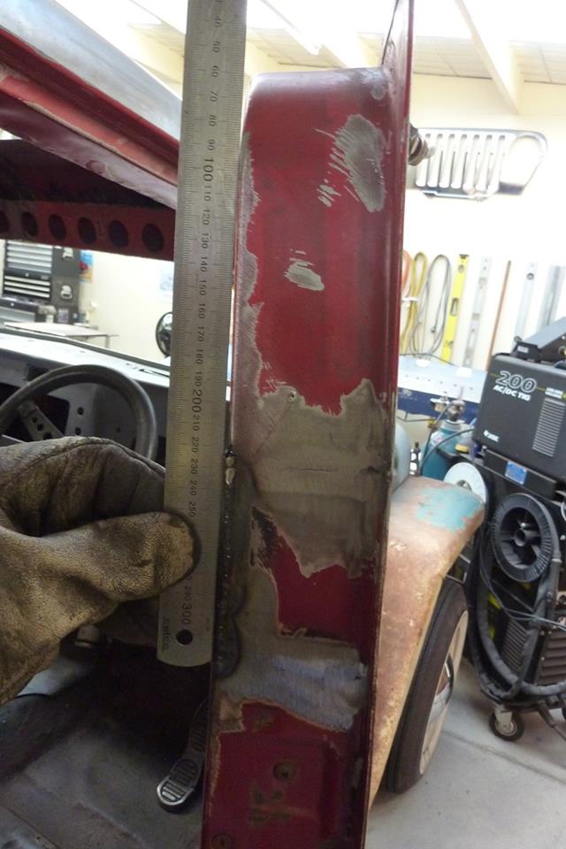 Bottom was cut and then pulled in only to the point where it lined up with the top of the frame. Pulling it to meet the bottom of the upper half would leave a dip which will show up once the straight window surround is against it. 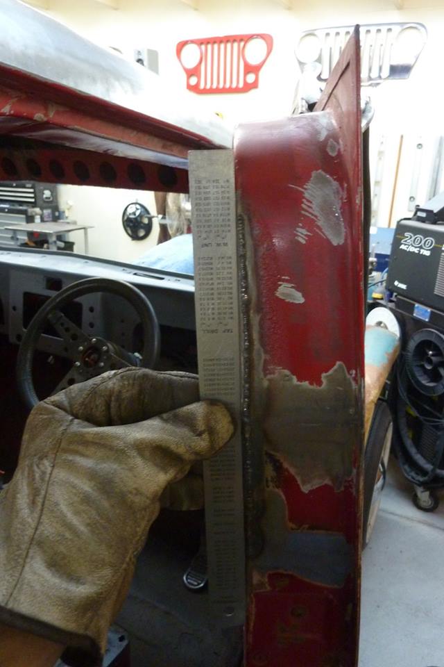 Top half cut and pulled out to meet the lower piece.  All finished up. 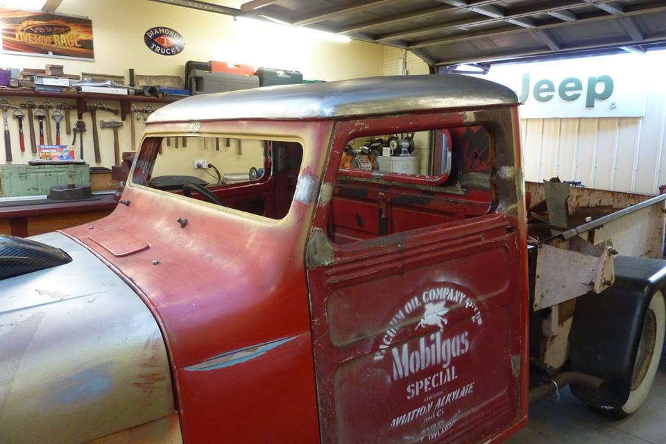 Now in my opinion the height difference between the windscreen and the door window is out of proportion to each other. It is why I sectioned the cab under the windscreen and chopped only the door window 2" to match it up. Unfortunately this only gets worse the bigger the chop if both windscreen and window is cut only such as here. 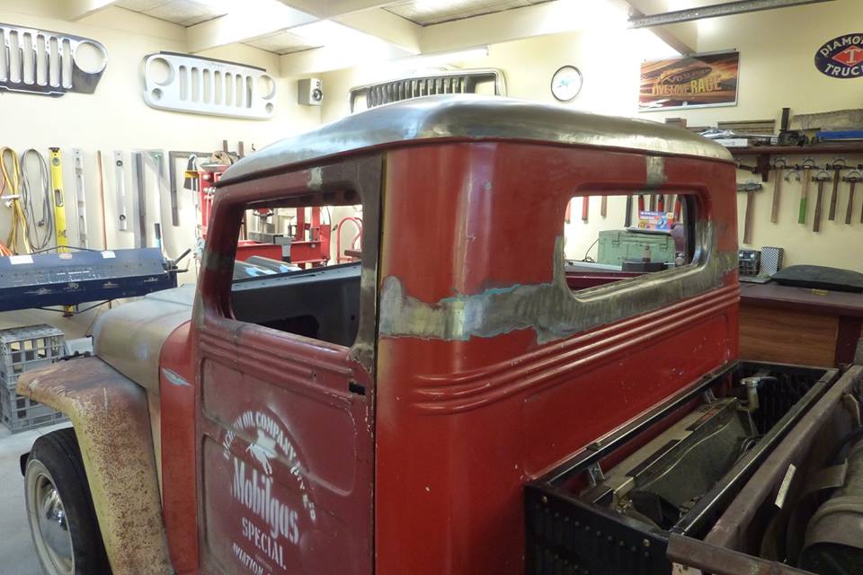 Same from the back view. 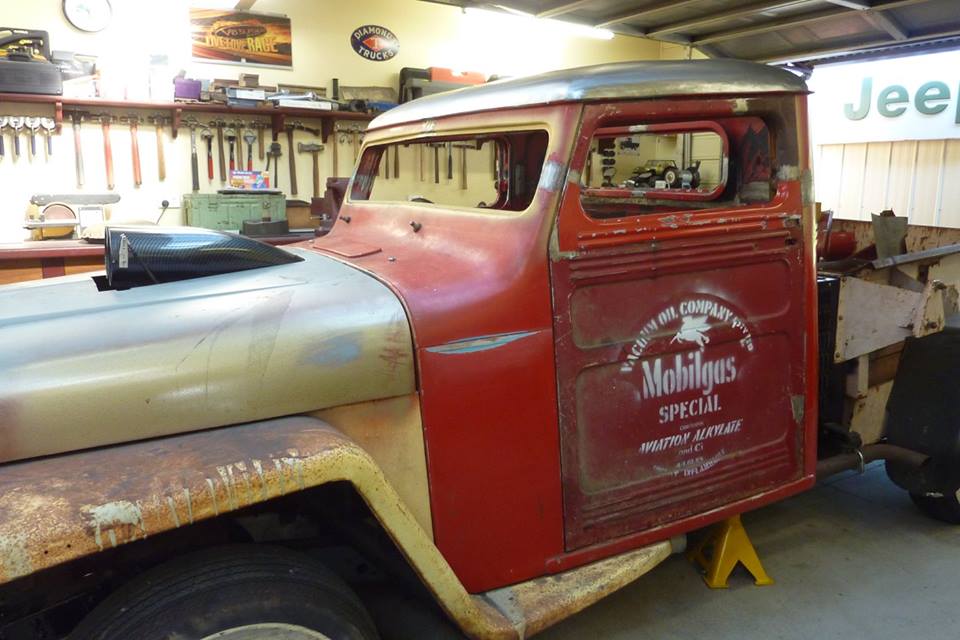 Now I had this idea to solve the problem another way many years ago before I sectioned mine the way I did. That is to raise the window sill instead. This mock up it is raised 50mm or 2" to match the height of the windscreen not including the flanges. 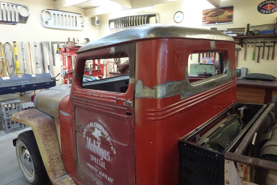 Rear view with 50mm-2" raised window sill. 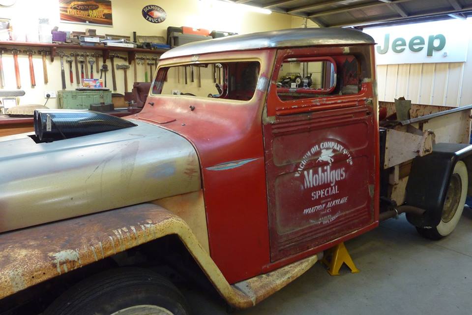 This is 65mm-2.5" which matches the opening of the windscreen including the flanges. 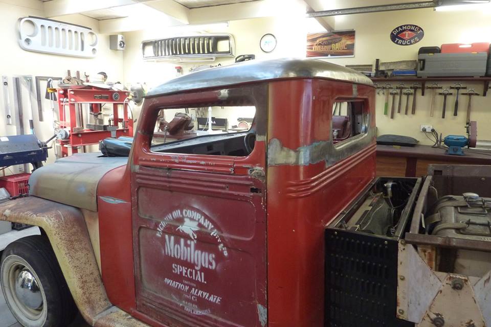 65mm-2.5" raised window sill. The inside frame would have to be raised as well to match of course and would not have the extra ribs. Just a thought anyway.
__________________
Marcus aka. Gojeep Victoria, Australia http://willyshotrod.com Invention is a combination of brains and materials. The more brains you use, the less materials you need.
|
|
#33
11-20-2017, 06:33 PM
|
|||
|
|||
|
Hello Marcus,
Don't forget that we Rat Rod Drivers like to drive with our arms hanging out the window and knuckles dragging on the Ground, so you might need to bare in mind the height of the bottom of the Window in relation to the seating arrangements 
__________________
Leigh, Stop moving so fast, you're creating a breeze.
|
|
#34
11-21-2017, 04:49 AM
|
||||
|
||||
|
Best solution is to lower the bottom of the windscreen like mine as maybe too 'high waisted' doing it this way.
__________________
Marcus aka. Gojeep Victoria, Australia http://willyshotrod.com Invention is a combination of brains and materials. The more brains you use, the less materials you need.
|
|
#35
11-21-2017, 05:15 PM
|
|||
|
|||
|
Quote:
and you could probably use the challenge....? maybe?
__________________
Kent http://www.tinmantech.com "All it takes is a little practical experience to blow the he!! out of a perfectly good theory." --- Lloyd Rosenquist, charter member AWS, 1919.
|
|
#36
11-21-2017, 10:14 PM
|
||||
|
||||
|
Quote:
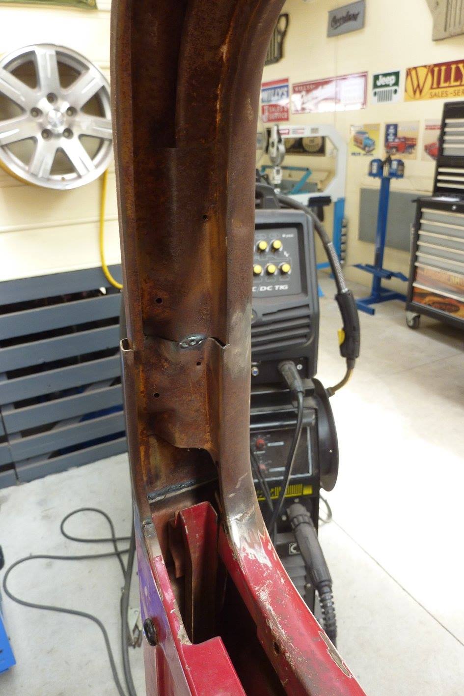 Like on the other door, I also fixed the inner frame alignment more than had been done. 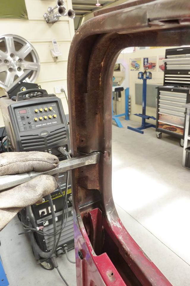 I had to cut through their tack and sharpened up the inside fold. The glass channel sits in this corner. 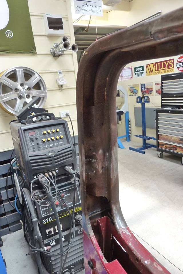 Needs a little more sharpening of the fold further down, but a lot better than it was before. Also had to do the same pulling out of the upper frame edge and pushing in the lower half to get a straight line on the edge. 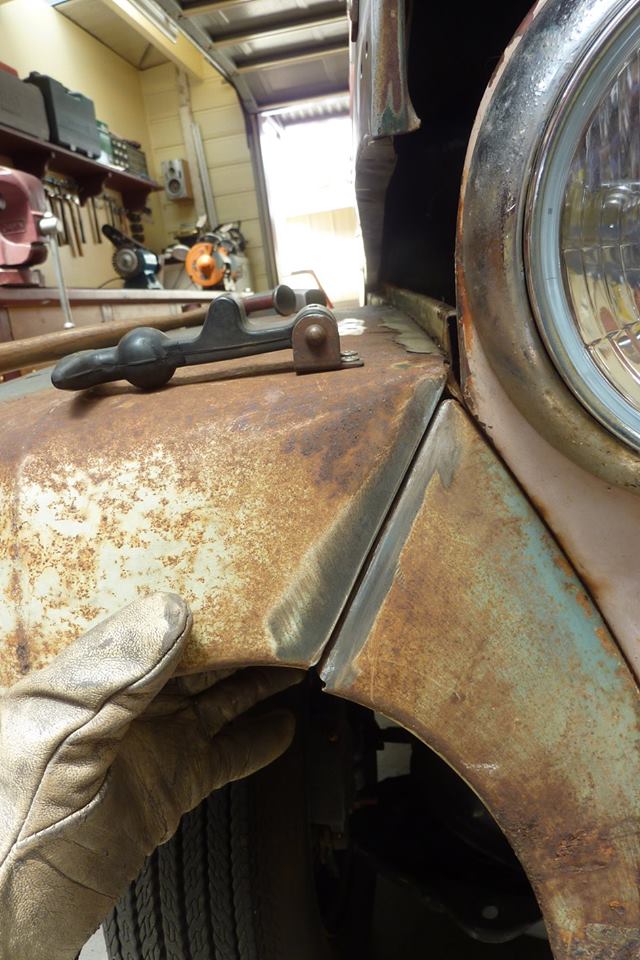 This seam had broken away so needs to be fixed. Noticed the bottom doesn't line up any more either. 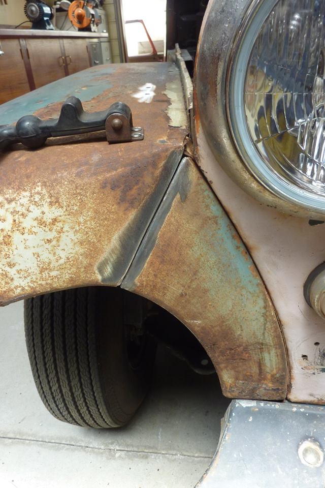 The guard needed to be knocked down to get it aligned at the bottom. 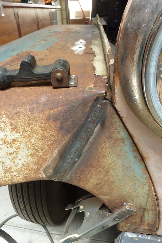 The whole seam this time was fully welded rather than just a few spot welds the factory had.  Dressed up.  The flapping about had caused yet another fatigue crack behind one already welded up. Was better to cut it away and make a new patch instead of just welding the crack.  Putting some compound curve in the patch by hammering over a steam pipe bend.  The flange width will be added below this line.  Starting to hammer over the flange.  All welded in. I also had to fix up a small crack on both sides where the inner guard meets the triangular piece under the bonnet. Always pays to go searching to see if the movement over time has caused any other damage.  Other seam also welded and old drill holes on both guards done also.
__________________
Marcus aka. Gojeep Victoria, Australia http://willyshotrod.com Invention is a combination of brains and materials. The more brains you use, the less materials you need.
|
|
#39
11-22-2017, 07:56 PM
|
||||
|
||||
|
Quote:
Quote:
 Originally the other place was going to weld these lengths of angle around the hole to stiffen it up. Would take some time in the shrinker stretcher to get them all to match perfectly. Then would have around 4 metres-13' of welding to fit them. Then grind, planish, sand, planish and run the strip disc over it and check for any distortion once again! Many many hours of work. 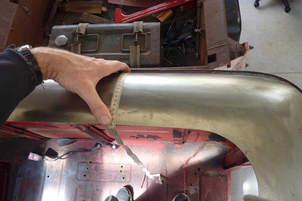 Thought I would check to see if the hole was an even distance all the way around like Christos had asked for. Not even close with even one side having over 15mm-9/16" difference from one end to the other! 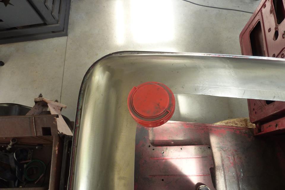 So took the shortest length and made that the same all the way around marking every couple of inches. Radius corner template a lid from my zip ties. 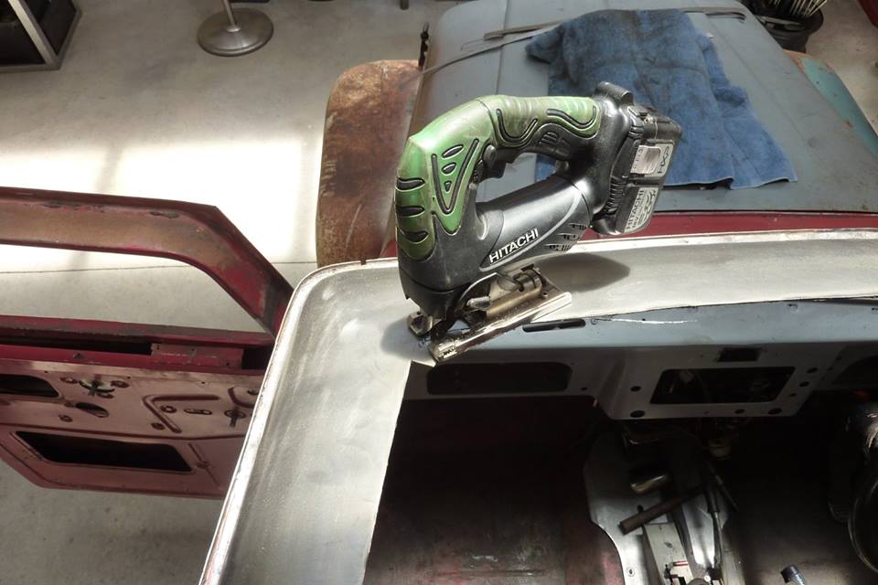 Cut the long lengths with a 1mm cut off disc and did the corners with my jigsaw. 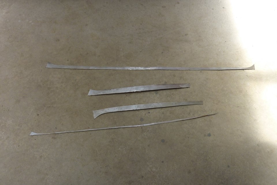 Pieces that needed to be cutout to make the distance even all the way around.  I got some 13mm-1/2" bar stock and cut down to the depth I wanted to tip the flange. Just used a 1mm cutoff disc and taped where I wanted to stop, 14mm-9/16".  Makes a good way to scribe a bending line to follow later too.  Slide the bar all the way in and bend down bit by bit. Actually found you could hold the same angle down and just knock the bar along and it would bend it down as you went along. Tape gives a good visual to make sure you are all the way in. 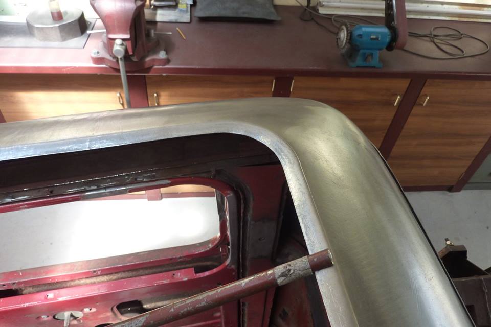 Corners are done the same way. 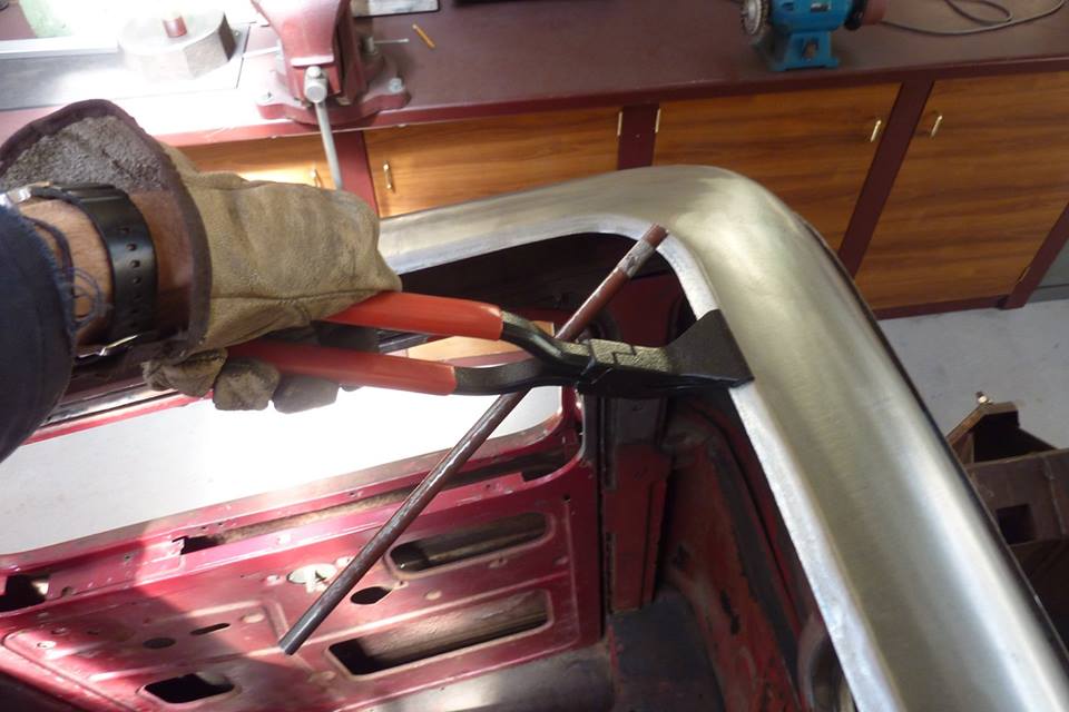 Once a couple of times around I switched to using my flanging pliers to speed things up along the straighter lengths. Bar was still used in the corners and kept at the same level of bend. 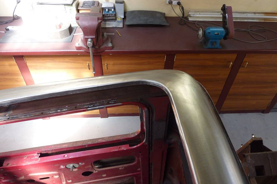 Probably took 6-7 times bending a little more getting the 90* bend. 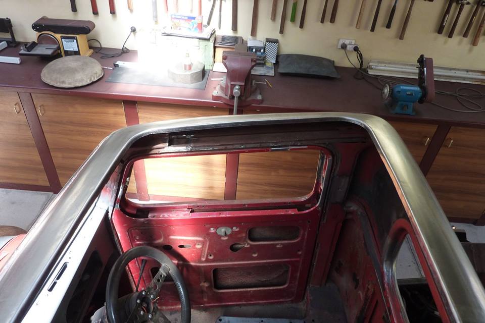 As you see it now only the bar and the flanging pliers have been used. 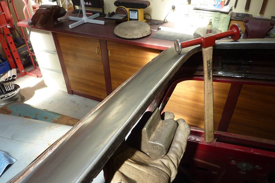 Was pretty close already but some fine tuning to even any highs or lows. With this dolly behind the flange, I hammered on dolly, stretching the metal, near the bend if I wanted to raise it. Hammered on dolly only at the bottom of the flange if I wanted to lower it some. 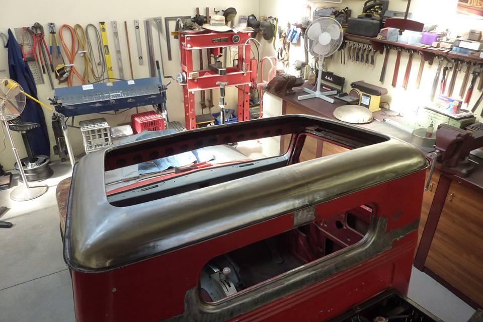 One nice and stiff roof panel ready for an insert later on that will be removeable.  The insert can bolt through the newly made flanges with T type rubber seal in between.
__________________
Marcus aka. Gojeep Victoria, Australia http://willyshotrod.com Invention is a combination of brains and materials. The more brains you use, the less materials you need.
|
|
#40
11-22-2017, 10:52 PM
|
|||
|
|||
|
A sincere thank you for the previous post. The thorough explanation of the manual tipping process that makes sense to me. That flange is nice enough to be the roof... Forget the insert. I like it as it is.
Making tools - check! Using tools - check! Clear process to follow - check! Elegant results - check! Holiday wishlist Metal rod Cutoff wheel Small hammer Metal in bad enough shape that I can't make it worse.
__________________
Rick in Washington, USA Here to quietly observe and learn.
|
 |
| Thread Tools | Search this Thread |
| Display Modes | |
|
|


 Linear Mode

